The Cross-sectional Morphology of the Mandible in the Premolar Region: A Retrospective Cone-Beam Computed Tomography Study
Jake Samuels, Alyssa Zhang, Paul Monsour
Department of Dento-maxillofacial Radiology, School of Dentistry, The University of Queensland, UQ Oral Health Centre, 288 Herston Road, Herston QLD 4006, Australia
Submission: 20 March 2020; Revision: 15 June 2020; Acceptance: 19 June 2020
ABSTRACT
Objectives:: The objectives of this study were to examine variations in the cross-sectional morphology of the mandible at the premolar region.
Materials and Methods: Two hundred and forty-three cone-beam computed tomography datasets, providing 486 sites, were reviewed to examine the cross-sectional morphology of the mandible in the premolar region.
Results:: A lingual concavity was detected in 14% of the sites examined. A buccal cavity was present in 17.9% of sites. In the presence of a buccal concavity, there was a statistically significant association between increased mandibular height (P = 0.002) and increased crest to neurovascular bundle distance (P < 0.001). There was no statistically significant difference in the mandibular height or ridge crest to the neurovascular canal distance, where there was a lingual concavity. The most common cross-sectional shapes observed in the premolar region of the mandible were straight-convex (26.3%), convex-convex (24.1%), and straight-straight (21.6%). The least common shapes were convex-concave (10.1%) and concave-concave (3.9%).
Conclusions: In this study, 28% of mandibular premolar sites had a concavity in the buccal and/or lingual cortical plate. It is clear that the lower premolar regions require considerable three-dimensional pre-implant planning not only due to the complex neurovascular elements but also due to the frequent presence of concavities in the buccal and/or lingual plates.
Key Words: Cone-beam computed tomography, Cross-sectional studies, Dental implants, Dentistry, Mandible
INTRODUCTION
The cross-sectional morphology of the mandible is becoming an increasingly important consideration when treatment planning for dental patients. This is primarily due to endosseous dental implants featuring heavily in the rehabilitation of edentulous sites. Knowledge of the cross-sectional shape of the mandible and position of key anatomic structures is critical to assessing the feasibility of available treatment options and preventing complications.
Conventional planar radiography, both extra-oral and intra-oral, provides a two-dimensional image of three-dimensional anatomic structures. The limitations of conventional planar radiography have been established, and the benefits of three-dimensional imaging in assessing the anatomy within the area of interest are clear and widely accepted.[1-6] The ability to reliably measure bone height and morphology from panoramic radiographs is questionable.[7] Despite the increasing reliance on three-dimensional datasets and treatment planning software, there is generally poor evidence within the literature to support the assertion that cross-sectional imaging is required for all pre-surgical implant planning.[8] A position statement from the American Academy of Oral and Maxillofacial Radiology recommends “some form of cross-sectional imaging be used for implant cases” yet clarifies, it should not be used as an initial diagnostic examination.[9,10] Since 2002, the European Association for Osseointegration has maintained the position that “if the clinical assessment of implant sites indicates that there is sufficient bone width and the conventional radiographic examination reveals the relevant anatomical boundaries and adequate bone height and space, no additional imaging is required for implant placement.”[3,11]
The use of multi-slice computed tomography (MSCT) and cone-beam computed tomography (CBCT) has largely superseded previous techniques for obtaining cross-sectional images in implant treatment planning such as planar tomography. Frei et al., in 2004, questioned the value of cross-sectional imaging for implant surgery in the posterior mandible, finding that clinical judgment was sufficient to establish bone width, and this could be confirmed at the time of the procedure.[2] This sentiment is not universally shared with many advocating for the use of cross-sectional imaging during implant treatment planning to assist with localizing the mandibular canal and establishing the buccolingual dimensions of the bone.[9,12-15]
The shape of the mandible is of interest when planning the placement of endosseous implants to avoid complications. Watanabe et al. showed that a round cross-sectional shape was the most common in the posterior region, followed by a lingual concavity shape.[16] Anteriorly, a buccal concavity was the most common shape, followed by a round shape.[16] Herranz-Aparicio et al. observed a similar frequency in the cross-sectional shape of the region of the first mandibular molar in 151 patients using CT. A U-ridge (lingual undercut) was seen in 64.2% of subjects, a P-type (parallel) ridge was present in 22.5% of subjects, and the C-type (convex) ridge was only seen in 13.2% of subjects.[17] Ciftci et al. observed that a C-shaped cross-sectional morphology was more common in the mandibular second premolar region, with a U-shape being the most common shape in the mandibular second molar region.[18] Chan et al. reported that lingual undercuts were present in a large percentage of subjects (66%), with a mean depth of 2.4 mm and a maximum recorded depth of 5.1 mm.[19]
The presence of buccal and/or lingual concavities may restrict the use of implant fixtures for the rehabilitation of edentulous sites in the mandible. This is due to insufficient buccolingual ridge width or risk of perforation due to a concave cortical profile. There are limited studies that assess the mandibular premolar region in cross section for both buccal and lingual concavities.[16,20] Most of the existing studies assessing the cross-sectional shape of the mandible appear to focus on the lingual concavities in the posterior body. This study aims to examine the variations in the cross-sectional morphology of the mandible, including the shape of the buccal cortex.
MATERIALS AND METHODS
Dental CBCT scans of Australian patients acquired in a radiology clinic from the year 2008 to 2017 were evaluated by a dentomaxillofacial radiology registrar. The scans were acquired using an i-CAT cone-beam CT (imaging sciences international) using 120 kV and 3–7 mA. The patient data were anonymized before the examination. The scans had been previously reviewed and reported by a registered dentomaxillofacial radiologist.
A total of 243 CBCT scans (107 males and 136 females) demonstrating the mandible and all mandibular premolars were randomly selected for inclusion. Cases demonstrating pathology or previous surgery in the mandibular premolar region were excluded from the study. The mean patient age at the time of the scan was 36.2 years.
The orientation of the three orthogonal planes was achieved by aligning the hard palate in the axial and sagittal planes. Reformatted cross-sectional images of the mandible between the first and second premolar were created from the DICOM datasets using DICOM viewing software in vivo 5 (Anatomage, San Jose, CA, USA). Required measurements were made using the linear measurement tools within the software. The contour of the buccal and lingual cortical plates in each case was evaluated and allocated to the classification system developed for the study [Figure 1]. An example of each shape is shown in Figure 2.
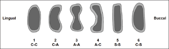
Figure 1: Classification of cross-sectional shapes observed in the mandibular premolar region
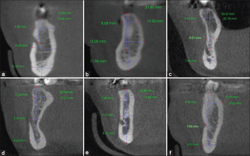
Figure 2: Example of cross-sectional shapes of the mandible in the premolar region. (a) Convex-convex, C-C. (b) Convex-concave, C-A. (c) Concave-concave, A-A. (d) Concave-convex, A-C. (e) Straight-straight, S-S. (f) Convex-straight, C-S. Note the lingual surface precedes the buccal surface
Statistical analysis was completed using JASP team (2019), JASP (Version 0.11.1) (computer software).
The ethics approval for this study was granted by the University of Queensland’s Dental Sciences Research Ethics Committee before commencement (Approval Number: 1838).
RESULTS
The 243 cases provided 486 sites in the premolar region of the mandible for evaluation. The most common cross-sectional shapes observed in the premolar region of the mandible were S-C (26.3%), C-C (24.1%), and S-S (21.6%). The least common cross-sectional shapes were C-A (10.1%) and A-A (3.9%). A column graph of the shapes is shown in Figure 3.
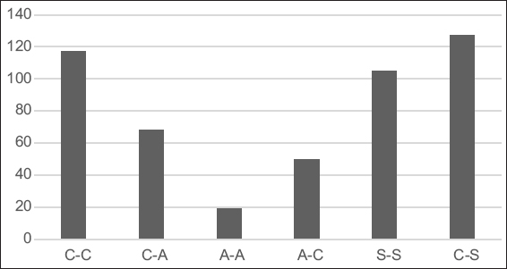
Figure 3: Distribution of cross-sectional shape
The presence of a lingual concavity was detected in 14% of the sites examined. The presence of a buccal cavity was present in 17.9% of sites. In this study, 28% of the sites in the mandibular premolar region had a concavity present in the buccal and/or lingual cortical plate. The majority of cases in this study had a straight or convex profile to the buccal and lingual cortical plates (72%).
The average height of the mandible in the premolar region was 35.9 mm. Where a prominent neurovascular canal was visible (inferior dental canal, mental foramen, or incisive canal), the mean height from the crest of the alveolar ridge to the canal was 15.92 mm.
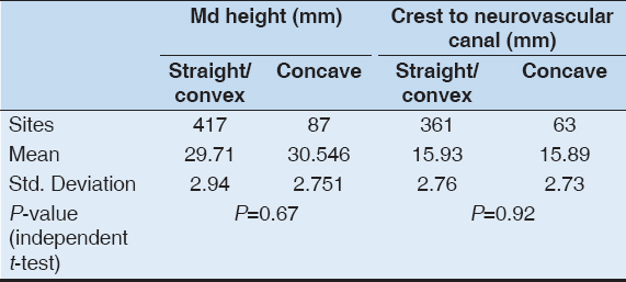
A statistically significant association was found between increased mandibular body height and the presence of a buccal concavity (P = 0.002) and increased alveolar crest to neurovascular canal distance and the presence of a buccal concavity (P < 0.001) [Table 1]. There was no statistically significant difference in the mandibular height, or in the distance from the ridge crest to the neurovascular canal, where there was a lingual concavity [Table 2].
Table 1: Mandibular height and distance from the crest of the alveolus to the neurovascular canal or foramen according to the morphology of the buccal cortical plate
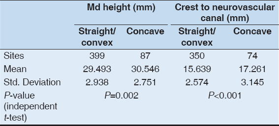
Table 2: Mandibular height and distance from the crest of the alveolus to the neurovascular canal or foramen according to the morphology of the lingual cortical plate
DISCUSSION
The presence of a buccal or lingual concavity, mental foramen, inferior dental, or mandibular incisive canal can all present as risks to the implant practitioner working in the mandibular premolar region. Injury to neurovascular structures or perforations of the cortices can occur without sufficient care treatment planning for surgical procedures. A thorough clinical and radiographic assessment of this area are important to reduce the risk of complications. Three-dimensional imaging such as CBCT and MSCT can produce reformatted images of the cross section of the mandible. CBCT has resulted in greater accessibility to three-dimensional imaging modalities in dental practice.
The results of this study differed significantly from those reported by Watanabe et al., who found that a buccal concavity was the most prevalent shape in the mandibular premolar region (58%) followed by a round shape (36%).[16] While the classification of shapes in this study varies to those used in others, the results obtained are similar to those found by Quirynen et al. who found a round shape to be the most common and the presence of a lingual concavity to be rare (2.4%).[20] Watanabe et al. speculated that the differences in the study completed by Quirynen et al. may be attributable to racial differences.[16] In this study, a lingual concavity was present in 14% of cases.
The association between a lingual undercut and deep position of the IAN in the posterior mandible reported by Nickenig et al. was not observed in the premolar region in this study.[21]
While there are numerous studies assessing the cross-sectional shape of the mandible in the molar region, there are only a few that examine the cross-sectional morphology of the mandible in the premolar region. The presence of a lingual concavity appears to be more common in the mandibular molar region than in the premolar region. In this study, the cross-sectional morphology in the mandibular premolar region was assessed in dentate patients. Further studies may be useful to compare the shape in edentulous premolar regions of the mandible due to the effect post-extraction changes may have on the cross-sectional morphology.
CONCLUSIONS
This study has shown that 28% of the sites in the mandibular premolar region may have a concavity in the buccal or lingual cortical plates. It is clear from this study that the lower premolar regions require considerable three-dimensional pre-implant planning not only due to the complex neurovascular elements but also due to the frequent presence of concavities in the buccal and/or lingual plates.
AUTHORS’ CONTRIBUTIONS
J.S, A.Z, and P.M conceived the ideas, P.M provided the cases, J.S collected the data, J.S analyzed the data, J.S and P.M led the writing, and A.Z edited the writing.
REFERENCES
1. Chan HL, Misch K, Wang HL. Dental imaging in implant treatment planning. Implant Dent 2010;19:288-98.
2. Frei C, Buser D, Dula K. Study on the necessity for cross-section imaging of the posterior mandible for treatment planning of standard cases in implant dentistry. Clin Oral Implants Res 2004;15:490-7.
3. Harris D, Horner K, Grondahl K, Jacobs R, Helmrot E, Benic GI,
4. Jacobs R, Quirynen M. Dental cone beam computed tomography:Justification for use in planning oral implant placement. Periodontol 2000 2014;66:203-13.
5. Koong B. Cone beam imaging:Is this the ultimate imaging modality? Clin Oral Implants Res 2010;21:1201-8.
6. Monsour PA, Dudhia R. Implant radiography and radiology. Aust Dent J 2008;53 Suppl 1:S11-25.
7. Tang Z, Liu X, Chen K. Comparison of digital panoramic radiography versus cone beam computerized tomography for measuring alveolar bone. Head Face Med 2017;13:2.
8. Shelley AM, Glenny AM, Goodwin M, Brunton P, Horner K. Conventional radiography and cross-sectional imaging when planning dental implants in the anterior edentulous mandible to support an overdenture:A systematic review. Dentomaxillofac Radiol 2014;43:20130321.
9. Tyndall DA, Brooks SL. Selection criteria for dental implant site imaging:A position paper of the American academy of oral and maxillofacial radiology. Oral Surg Oral Med Oral Pathol Oral Radiol Endod 2000;89:630-7.
10. Tyndall DA, Price JB, Tetradis S, Ganz SD, Hildebolt C, Scarfe WC,
11. Harris D, Buser D, Dula K, Grondahl K, Haris D, Jacobs R,
12. Bolin A, Eliasson S, von Beetzen M, Jansson L. Radiographic evaluation of mandibular posterior implant sites:Correlation between panoramic and tomographic determinations. Clin Oral Implants Res 1996;7:354-9.
13. Schropp L, Wenzel A, Kostopoulos L. Impact of conventional tomography on prediction of the appropriate implant size. Oral Surg Oral Med Oral Pathol Oral Radiol Endod 2001;92:458-63.
14. Lindh C, Petersson A, Klinge B. Measurements of distances related to the mandibular canal in radiographs. Clin Oral Implants Res 1995;6:96-103.
15. Peker I, Alkurt MT, Michcioglu T. The use of 3 different imaging methods for the localization of the mandibular canal in dental implant planning. Int J Oral Maxillofac Implants 2008;23:463-70.
16. Watanabe H, Abdul MM, Kurabayashi T, Aoki H. Mandible size and morphology determined with CT on a premise of dental implant operation. Surg Radiol Anat 2010;32:343-9.
17. Herranz-Aparicio J, Marques J, Almendros-Marques N, Gay-Escoda C. Retrospective study of the bone morphology in the posterior mandibular region. Evaluation of the prevalence and the degree of lingual concavity and their possible complications. Med Oral Patol Oral Cir Bucal 2016;21:e731-6.
18. Ciftci ME, Aktan AM, Isman O, Yildirim E. Relationship between CBCT and panoramic images of the morphology and angulation of the posterior mandibular jaw bone. Surg Radiol Anat 2016;38:313-20.
19. Chan HL, Brooks SL, Fu JH, Yeh CY, Rudek I, Wang HL. Cross-sectional analysis of the mandibular lingual concavity using cone beam computed tomography. Clin Oral Implants Res 2011;22:201-6.
20. Quirynen M, Mraiwa N, van Steenberghe D, Jacobs R. Morphology and dimensions of the mandibular jaw bone in the interforaminal region in patients requiring implants in the distal areas. Clin Oral Implants Res 2003;14:280-5.
21. Nickenig HJ, Wichmann M, Eitner S, Zoller JE, Kreppel M. Lingual concavities in the mandible:A morphological study using cross-sectional analysis determined by CBCT. J Craniomaxillofac Surg 2015;43:254-9.